


Angle connector type HS for high-quality load-bearing wood/wood connections
ANGL-WOCON-48X48X90X3,0

Register now and access more than 125,000 products
- Robust design and versatile use.
- Hot-dip galvanised sheet metal on both sides (DX51D + Z275 (approx. 20 µm)) in 3 mm thickness in accordance with EN 10327:2004.
- Application in utilisation class 1 and 2 in accordance with EN 1995:2013.
European Technical Approval ETA 09/0133
- The ring-shank/grooved nails should be driven in as close to the deflection curve in the load-bearing joist as possible.
- Load tables and detailed installation instructions can be found on the service page www.wuerth.de/holzverbinder.
European Technical Approval ETA 09/0133
Subject to technical changes!
Datasheets(X)

Load-bearing connections of timber joists to wood such as joist to joist and purlin to joist.
Suitable fasteners
- Ring-shank/grooved nails in accordance with EN 14592: 4.0 x 40 mm
- ASSY 4.0 Combi in accordance with ETA 11/0190: d = 12 mm
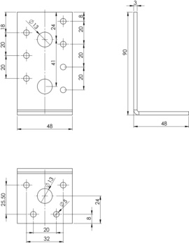 | |
Type | HS |
Width x height x depth | 48 x 90 x 48 mm |
Thickness | 3 mm |
Number of D 13 mm holes in subcarrier nJ/main carrier nH | 2 + 1 PCS |
Number of D 5 mm holes in subcarrier nJ + main carrier nH | 7 + 4 PCS |
Approval | ETA-09/0133 |
Product weight (per item) | 127.180 g |
Material | Steel |
Surface | Hot dip galvanized |
Weight | 140 g |
Material designation | DX51D |
Material standard | DIN EN 10327:2004 |
Number of D 5 mm holes | 11 PCS |
Number of D 13 mm holes | 3 PCS |
| Characteristic load-bearing capacities in kN of angle brackets type HS according to ETA-09/0216 with anchor nails - purlin/post | |||||||||||
| HS angle bracket | Article number | ETA | Anchor nail in | HS angle bracket per connection | |||||||
| F1,Rk | F2/3,Rk | F4,Rk | F5,Rk | ||||||||
| Width x length x depth x thickness in mm | Wood | Steel | Wood | Wood | Steel | Wood | Steel | ||||
| mm | kN | kN | kN | kN | kN | kN | kN | ||||
| 1 bracket HS | 48x90x48x3 mm | 0681 048 48 | 09/0133 | 4x40 | 1,01 | 1,74 | 2,62 | - | - | - | - |
| 48x90x76x3 mm | 0681 048 76 | 09/0133 | 4x40 | 1,01 | 3,02 | 3,36 | - | - | - | - | |
| 48x90x116x3 mm | 0681 048 116 | 09/0133 | 4x40 | 2,01 | 4,39 | 6,80 | - | - | - | - | |
| 2 brackets HS | 48x90x48x3 mm | 0681 048 48 | 09/0133 | 4x40 | 2,01 | 3,48 | 5,23 | 4,33 | 5,31 | 4,33 | 5,31 |
| 48x90x76x3 mm | 0681 048 76 | 09/0133 | 4x40 | 2,01 | 6,04 | 6,73 | 7,26 | 8,49 | 7,26 | 8,49 | |
| 48x90x116x3 mm | 0681 048 116 | 09/0133 | 4x40 | 4,03 | 8,79 | 13,60 | 11,39 | 13,07 | 11,4 | 13,1 | |
| 3) If one angle bracket is used for each connection, the connected component must be secured against twisting. 4) The loads F4 and F5 act on the top edge of the connected component. Securing against twisting is not required. The specified load-bearing capacities apply to softwood at 350 kg/m³ ≤ rk ≤ 420 kg/m³. For wood at 290 kg/m³ ≤rk≤ 350 kg/m³, the specified load-bearing capacities for wood must be multiplied by the factor kdens: tSteel ≥ 2.5 mm: kdens = (pk/350)^2 tSteel = 1.5 mm: kdens = (pk/350)^0.8 Design values of load-bearing capacities: Fi,Rd = min {Fi,wood,Rd; Fi,steel,Rd} Failure of fasteners in wood: Fi,wood,Rd = kmod/ƳM,wood × Fi,wood,Rk with ƳM,wood = 1.3 Steel failure of the connector: Fi,steel,Rd = Fi,steel,Rk/ƳM,steel with ƳM,steel = 1.25 For several simultaneous loads, the following condition must be met: The specified nailing patterns must be observed in accordance with the relevant ETA. | |||||||||||
| NOTE: These are guides for planning purposes. The values must be calculated for each project by authorised persons. | |||||||||||
| Characteristic load-bearing capacities in kN of angle brackets type HS according to ETA-09/0216 with anchor nails - purlin/post | |||
| HS angle bracket | eB | z | (1+eB/z) |
| 48x90x48x3 mm | 24 | 24 | 2,0 |
| 48x90x76x3 mm | 24 | 24 | 2,0 |
| 48x90x116x3 mm | 24 | 24 | 2,0 |
| FB,Ed=F1,d x (1+eB/z) If the load F4 or F5 acts with a higher eccentricity "e" than the top edge of the angle, an additional ΔF1 load must be applied to both angles. This is applied at the angles by an additional momentum and a pair of forces. B is the distance between the angles (width of the component to be connected). ΔF1,d = F4,d / F5,d x e/B | |||
Select RAL-colour code
!! NOTE: On-screen visualisation of the colour differs from real colour shade!!
Last viewed

ORSY BULL basic set of partition elements for customised partitioning of ORSY BULL top loader boxes

Lambswool polishing pad, white

Microfbre cloth, professional

Clamping pin/clamping sleeve, slotted, heavy-duty design ISO 8752 spring steel plain

Hexagon socket set screw with truncated cone ISO 4026 steel 45H, plain

Ward file

Hexagon socket set screw with ring cutter ISO 4029, steel, 45H, plain

Hexagon nut with fine thread DIN 934, steel I8I, zinc-plated, blue passivated (A2K)

Hexagon bolt with shank ISO 4014, A4-50 and A4-70 stainless steel, plain

Hexagon bolt with shank DIN 931, steel 8.8, zinc-plated, blue passivated (A2K)